
The BFS 20 datasheet provides mounting, ratings, electrical characteristics and thermal specifications for the surface‑mount high‑frequency transistor.
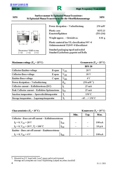
The document describes the BFS 20 surface‑mount transistor packaged in a plastic SOT‑23 (TO‑236) case. It specifies a 3 mm² copper pad for each terminal and details the standard taped‑and‑reeled packaging.
Electrical ratings include a 20 V collector‑emitter voltage, 30 V collector‑base voltage, 4 V emitter‑base voltage, 250 mW maximum power dissipation, and a collector current of 25 mA. Thermal data list a junction temperature of 150 °C, storage range –65 °C to +150 °C, and a junction‑to‑ambient thermal resistance of 420 K/W. Gain, frequency and capacitance parameters are also provided. This manual is written in German.
| Package type | SOT‑23 (TO‑236) |
|---|---|
| Copper pad size | 3 mm² per terminal |
| Maximum power dissipation | 250 mW |
| Collector‑Emitter voltage (VCE0) | 20 V |
| Collector‑Base voltage (VCB0) | 30 V |
| Emitter‑Base voltage (VEB0) | 4 V |
| Maximum collector current (IC) | 25 mA |
| Peak collector current (ICM) | 25 mA |
| Junction temperature (Tj) | 150 °C |
| Thermal resistance (RthA) | 420 K/W |
The maximum power dissipation is 250 mW.
A 3 mm² copper pad is recommended for each terminal.
The junction‑to‑ambient thermal resistance is 420 K/W.