
Instruction manual for Barber‑Colman Series EA electric actuators covering specifications, installation, wiring and operation.
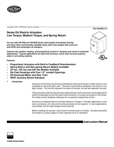
The manual provides an overview of the Series EA low‑torque, medium‑torque and spring‑return electric actuators, including part‑number identification, environmental limits and basic features such as built‑in feedback potentiometers and optional auxiliary switches. It describes the intended applications for damper and valve control in industrial heating, cooling and exhaust systems.
Detailed sections cover electrical input options, torque ratings, mounting dimensions, wiring diagrams, installation procedures for both damper and valve assemblies, and adjustment of limit switches and converters. The document also includes tables of model codes, converter options, and recommended power‑wire sizing for 24 Vac, 120 Vac and 240 Vac models.
| Input voltage options | 24 Vac, 120 Vac and 240 Vac |
|---|---|
| Ambient temperature range | -40 °F to 136 °F (-40 °C to 58 °C) |
| Power consumption | 28 W, 50 VA |
| Feedback potentiometer value | 100 Ω |
| Maximum 24 Vac wire run (14 AWG) | 115 ft (35 m) |
They can operate from –40 °F to 136 °F (–40 °C to 58 °C).
Invert the leads at terminals 2 & 3 and at terminals 7 & 8 of the actuator terminal block.
Use the power‑wire sizing table: 14 AWG for up to 115 ft, 12 AWG for up to 180 ft, or 10 AWG for up to 285 ft of 24 Vac cable.
All standard actuators are equipped with a 100 Ω feedback potentiometer.