
Installation and maintenance guide for the A‑T Controls EPR Series electro‑pneumatic positioner, covering setup, wiring, adjustment, and troubleshooting.
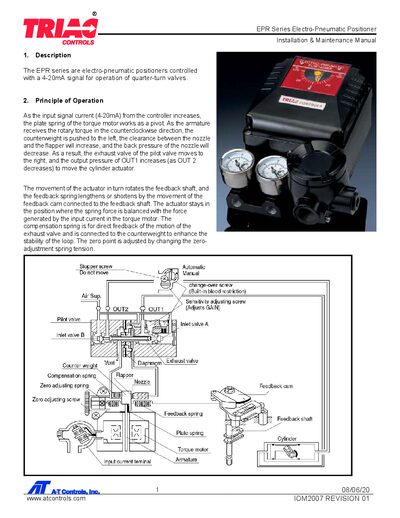
This manual provides detailed instructions for installing, wiring, adjusting, and maintaining the EPR Series electro‑pneumatic positioner. It includes safety warnings, specifications, and step‑by‑step procedures for mounting, cam adjustment, zero‑span setting, and optional pilot‑valve modifications.
Key sections cover the device’s principle of operation, electrical connections, air‑supply requirements, troubleshooting tips, and dimensions. The guide is intended for technicians and engineers responsible for valve control systems.
| Input Signal | 4‑20 mA |
|---|---|
| Input Resistance | 235 ± 15 Ω |
| Air Supply Pressure (max) | 100 PSI (oil‑free) |
| Standard Stroke | 60°‑100° |
| Air Piping Connection | ¼" NPT |
| Conduit Connection | ½" NPT |
| Protection Rating | IP66; ATEX/IECEx Ex dmb IIC T6/T5 Gb |
| Ambient Temperature Range | -4 °F to 158 °F |
| Linearity | ± 1.5 % F.S |
| Air Consumption (20 PSI) | 0.18 CFM |
Ensure the air supply to the positioner is shut off before adjusting or replacing cams to prevent sudden movement that could cause injury or damage.