
This document is the user manual for LinkTrack V2.0, which introduces the product usage and precautions.
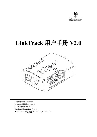
LinkTrack S and LinkTrack P user manual V2.0 covers basic use of the LinkTrack system, including power supply options, node installation methods, antenna orientation, obstruction effects, and DOP. It also states firmware V4.0.0, N protocol V1.3, and NAssistant V4.0.1 versions.
The manual provides quick-start procedures for LP, DR, and DT modes, NAssistant wireless settings, firmware updates, recording, replay and export, variable definitions, NLink and NMEA-0183 protocol unpacking, one-button calibration, FAQ, and update log. This manual is written in Chinese.
| Firmware version | V4.0.0 |
|---|---|
| N protocol version | V1.3 |
| NAssistant version | V4.0.1 |
| Product series | LinkTrack S, LinkTrack P |
| Recommended power cable length | not more than 3 m |
| Battery standard voltage | 3.7 V |
| Battery full-charge voltage | 4.2 V |
| Tripod mounting hole | 1/4-20 |
| Carrier mounting holes | 2 M3 |
| Solid wall penetration | LTS: 1 wall; LTP: 2-3 walls |
| Positioning error increase per wall | about 30 cm |
| Glass wall thickness with small effect | not greater than 3 cm |
Common power supply devices include charging banks, adapters, and batteries.
LTS can pass through 1 solid wall, and LTP can pass through 2-3 solid walls.
The direct power supply cable length is not recommended to exceed 3 meters.
Glass no thicker than 3 cm has little effect on UWB positioning accuracy and distance attenuation.