
This document is Turf Pro TM user guide, which provides detailed introduction of the product features and characteristics, including specifications, remote control compatibility, Anywhere Programming, Memory Protection, Rain Sensor Operation, Buttons and Switches, Rotary Dial, Installation, Getting the Most Out of Your Turf Pro, Getting Started, Automatic Operation, Special Features, Water Budget etc.
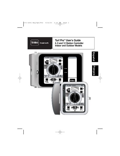
This user's guide covers the Turf Pro 6, 9 and 12 station irrigation controller in both indoor and outdoor models. It explains the controller's specifications, the function of each button, switch and rotary dial setting, and how the removable control module, memory protection and optional rain sensor and EZ-Remote system work.
The installation section describes mounting the controller, connecting an earth ground, wiring valves, a master valve or pump start relay, a rain sensor and the power source. Later sections walk through setting the time and date, building watering schedules, using the water budget and special functions, starting and stopping watering manually, and troubleshooting the system.
| Input (outdoor models, internal transformer) | 120 V a.c., 60 Hz, 30 VA (domestic) |
|---|---|
| Input (indoor models, external transformer) | 24 V a.c., 60 Hz, 30 VA (domestic) |
| Output | 24 V a.c. at 1.0A total maximum output; 0.5A maximum per station |
| Master Valve/Pump Start Relay Output | 24 V a.c. at 0.375A (maximum) |
| Operating temperature range | 32˚F to 140˚F (0˚C to 60˚C) |
| Battery back-up | One 9-volt alkaline (included) |
Set the two-position sensor switch to the BYPASS position or attach the jumper wire to both sensor terminals; the controller will not operate automatically with the switch in the ACTIVE position and no sensor or jumper installed.
Settings are stored in non-volatile memory and retained for up to 10 years even without battery power; a new battery maintains the current date and time for 48 hours.
Pull forward on the right edge of the module, unplug the ribbon cable connector from the printed circuit board, then unsnap the module from its hinges; reverse the steps to reinstall.
It is designed for 24 V a.c., 0.25A (6 VA) solenoid-operated valves, with a maximum of two solenoids per terminal and no more than three solenoids on at one time plus the master valve or pump start.