
Describes the function and installation method of RAK-LINK
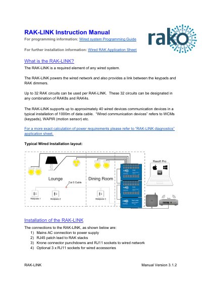
The RAK-LINK is a required element of any wired system. It powers the wired network and provides a link between keypads and RAK dimmers, supporting up to 32 RAK circuits in any combination of RAK8s and RAK4s.
The manual covers installation steps, termination jumper settings for daisy chain or star configurations, programming with Rasoft pro software, and diagnostic LED status troubleshooting.
| RAK circuits per unit | Up to 32 |
|---|---|
| Wired devices supported | Up to approximately 40 in a typical 1000 m data cable installation |
| Optional wired accessory ports | 3 x RJ11 sockets |
| Diagnostics board requirement | ISSUE B circuit board and firmware version 0.4.6 |
Up to 32 RAK circuits can be used per RAK-LINK, in any combination of RAK8s and RAK4s.
It supports up to approximately 40 wired communication devices in a typical installation of 1000 m of data cable.
No Term uses both jumpers removed, Term uses jumpers across 1+2 and 4+5, and Star Term uses jumpers across 2+3 and 5+6.
The RAK-LINK is programmed using Rasoft pro programming software, and a WK-HUB or WA/WTC-Bridge is required for any programming of a wired system.