
This manual provides technical information about the Alpha Technologies Enhanced Digital Status Module (EDSM) to assist users with product installation, configuration, operation and maintenance.
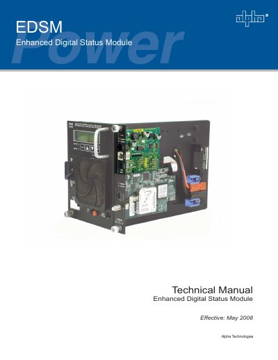
This technical manual covers the Alpha Technologies Enhanced Digital Status Module (EDSM), a status monitoring interface for the XM Series 2 power supply. The document is identified as 704-721-C0-004, Rev. D, effective May 2008, and describes how the EDSM collects power supply, generator and battery data and passes it to an industry standard digital transponder (DT) over a serial interface specified by the ANSI/SCTE25-3 standard.
The manual covers connectors and indicators, including the LED indicators, STAT switch, COM connector, tamper connector, DIP switch and headers, followed by module installation and the XMS2 communication module removal procedure. It also includes safety notes, general safety precautions, a system layout diagram, alarm codes, DIP switch settings and a troubleshooting table.
| Power supplies monitored | Up to six |
|---|---|
| Battery strings monitored | Up to two, via the AUX connector |
| Generator monitored | One AlphaGen generator |
| Data interface | Serial interface to a digital transponder (DT), per ANSI/SCTE25-3 |
| Part number (EDSM with DT Connector) | 745-678-20 |
| Part number (legacy EDSM) | 745-678-21 |
| EMC classification | Class 'B' when configured in an Alpha UPS |
| Alpha Bus communications | RS-485 |
It can monitor up to six power supplies and an AlphaGen generator, and up to two battery strings can be monitored directly using the AUX connector.
The DT connector is only used for connecting to an external digital transponder; connecting any other device may damage the EDSM and associated equipment.
It indicates active communications on the RS-485 Alpha Bus, the internal communications link between the EDSM and the power system.
The EDSM with DT Connector is Alpha P/N 745-678-20, and Alpha P/N 745-678-21 is listed as the legacy product.