
This is a setup guide for FTC61, which mainly introduces how to connect the controller and motor.
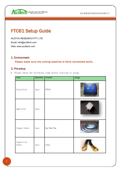
This guide covers setup of the Aosendike FTC61 controller for a cutting machine. It lists required items and describes controller and motor connections, cabling, input configuration, power-up checks, and calibration.
It includes port functions, input defaults, wiring resistance checks, and calibration steps using a 20*20 cm steel sheet.
| DC power input | 24 V, 1 A |
|---|---|
| Signal cable length | 6 m / 10 m / 15 m |
| Capacitive cable length | 15 cm |
| COM output level | Low level for 0 V, high level for 5-24 V |
| Input defaults | DI1-DI6 passive, high level |
| Calibration sheet size | 20 x 20 cm |
Make sure the cutting machine is fairly connected to earth.
All tested resistances should be under 10 Ω.
Turn off the system and check whether the W, V, W connection is correct.
Use a flat 20*20 cm steel sheet.