
This document is about the technical manual for the installation of Hammond butterfly valves
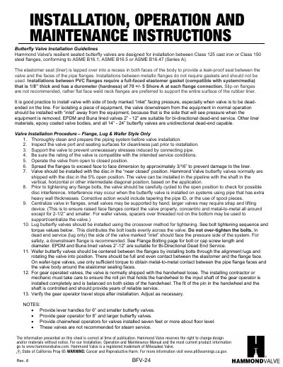
This guide provides step-by-step instructions for installing Hammond Valve butterfly valves between flanges, including torque specifications and alignment procedures. It covers installation for flange, lug, and wafer styles, with specific guidance for different valve sizes and materials. The guide also includes operation details, such as handwheel installation and gear operator adjustment, and maintenance recommendations, including periodic cycling to prevent material buildup.
| Flange Compatibility | Class 125 cast iron or Class 150 steel flanges, conforming to ASME B16.1, ASME B16.5 or ASME B16.47 (Series A) |
|---|---|
| Elastomer Seat | Lapped over into a recess in both faces of the body to provide a leak-proof seal |
| Gasket Requirement for PVC Flanges | Full-faced elastomer gasket, 1/8” thick, durometer 70 +/- 5 Shore A |
| Recommended Flange Type | Flat face weld neck flanges |
Class 125 cast iron or Class 150 steel flanges, conforming to ASME B16.1, ASME B16.5 or ASME B16.47 (Series A).
Flat face weld neck flanges are preferred to support the entire surface of the rubber liner.
Install the valve with the side marked “inlet” facing pressure, especially when dead-ended on the line.
5/8” fasteners, 15 - 45 ft-lbs.