
This document details the decoder system, including system background, product introduction and connection methods.
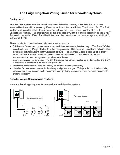
This document provides a wiring guide for Paige Electric decoder systems used in the irrigation industry. It details the history of decoder systems, compares them to conventional systems, and explains the tradeoffs regarding wire quantity, reliability, and maintenance. The guide includes specific wiring diagrams for both single and multi-solenoid decoders.
| Minimum wire burial depth for voltages > 30V | 24 inches |
|---|---|
| Minimum wire burial depth for voltages <= 30V | 6 inches |
| Bonding wire size for decoder ground grids | 10 AWG solid bare copper |
| Recommended burial depth for bonding/shielding wire | 8"-12" deep |
Wire quantity is reduced in decoder systems and replaced with decoders.
Decoders contain electronic components which are susceptible to lightning damage.
There is more than twice the number of splices in a decoder system than in a conventional system.