
Introduces Suzuki Engine Interface installation methods, including pre-installation preparation, installation steps and precautions.
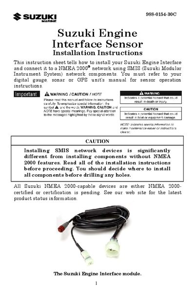
The Suzuki Engine Interface sensor converts engine data into NMEA 2000 format and connects to the boat's network via black Devicenet connectors. The guide explains the required tools, wiring, and network topology needed for proper installation.
Step‑by‑step instructions cover mounting the sensor, routing cables, attaching the interface and trim connectors, and configuring the device through the gauge menu, including fuel warnings and reset functions.
| Extension cable length | 2 foot |
|---|---|
| Network requirement | NMEA 2000 network |
You can install up to three Suzuki Engine Interface sensors, one for each engine.
Only the AT connector is required, along with the supplied extension cable, T connector, and terminators.
Select Fuel Warning in the System Setup menu, choose Low or High level, and set the desired percentage.
The cable must not contact moving parts or hot engine components and should have enough slack for engine movement.