
This document is the EIP user guide published by NASA Airborne Sensor Facility, which introduces EIP's functions, interfaces, and usage methods
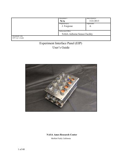
The Experiment Interface Panel (EIP) is a standard power and data interface for instruments flying on board NASA Airborne Science platforms. It supplies AC (3-phase, 400Hz), DC (28V), and switched contacts to power and control experiments, with Ethernet as the primary data interface and support for legacy protocols like RS-232 and ARINC-429.
This document serves as a user's guide for the EIP, detailing quick start procedures for bench operation, payload and observatory interfaces, mechanical specifications, and troubleshooting steps. It includes specific instructions for connecting DC and AC power supplies, configuring switches, and understanding the status packet format.
| DC Power (Per Circuit) | 420W maximum per circuit @ 28VDC |
|---|---|
| DC Power (Total EIP) | 2.2kW maximum per EIP |
| AC Power (Per Circuit) | 5.175kVA / circuit |
| AC Power (Total EIP) | 17.25k VA maximum per EIP |
| DC Input Voltage Range | 4V to 36VDC |
| AC Input Voltage | 115 VAC, 400Hz on 3 phases |
| Standby Current Draw | about 350mA |
The primary data interface is Ethernet, though the EIP also offers connections for legacy protocols such as RS-232, ARINC-429, IRIG-B, and Synchro.
The EIP status broadcasts should have an IP address of 10.3.0.15.
For high current power supplies, the output should be limited to 35A maximum.