
Control card RK 4003 is the centerpiece of a control loop, receiving all the necessary signals for the control system and triggering the motor to change the position of the actuator. It ensures the coordination between the actual and set positions. The control card consists of a processor, memory chip, DIP switch for device address, JST socket-contacts, terminals, green LED (for operating voltage), and yellow LED (for display). The document provides detailed information on parameter lists, parameter explanations, technical data, etc.
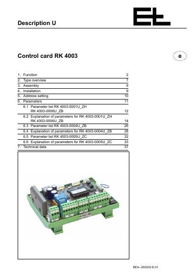
The document describes the E+L Control Card RK 4003, which serves as the centerpiece of a control loop by receiving signals and triggering motors to adjust actuator positions. It covers various operating modes including manual positioning, centering, automatic guiding, web offset, and oscillation.
The guide provides specific instructions for assembly and installation, noting requirements for heat dissipation and wiring distances. It details parameter lists for different card variants (RK 4003-0001U_ZH, RK 4003-0006U_ZB, etc.) and explains control structures for proportional, integral, and continuous-action actuators.
The connecting line may be run in a cable up to a length of 3 m.
The maximum distance to the DC actuator may not exceed 10 m.
If an output power greater than 20 W is required, the power transistor heat sink must be mounted.