
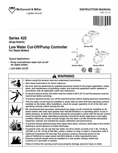
This document is an instruction manual for the MM-231G 246736 pump circuit. The document provides detailed information on the pump's circuit ratings, voltage, differential settings, operating distances, etc.
This document provides installation instructions for the McDonnell Miller MM-231G 246736 Low Water Cut-Off/Pump Controller. It details the tools required, the specific steps for mounting the control on vertical equalizing pipes, and the correct positioning relative to the boiler's water level and gauge glass tappings.
| Voltage | 120 VAC or 240 VAC |
|---|---|
| Full Load Amperes (120V) | 7.4 A |
| Locked Rotor Amperes (120V) | 44.4 A |
| Pilot Duty VA (120V) | 345 VA |
| Full Load Amperes (240V) | 3.7 A |
| Locked Rotor Amperes (240V) | 22.2 A |
| Pump Off Setting | 1 3/8 in (35 mm) |
| Pump On Setting | 5/8 in (16 mm) |
| Burner On Setting | 7/8 in (22 mm) |
| Burner Off Setting | 0 in (0 mm) |
| Maximum Pressure | 50 psi (3.5 kg/cm²) |
| Motor Horsepower | 1/3 Hp |
| Warranty | 1 year from installation or 2 years from manufacture |
Two pipe wrenches, one flathead screwdriver, and pipe sealing compound are needed.
The horizontal cast line on the body should be 1 3/8 in (35 mm) below the boiler's normal water level.
With the boiler empty, the pump should go on and the burner must remain off.
The burner should come on when the water level reaches approximately 7/8 in (22 mm) above the horizontal cast line.