
This document describes the features and characteristics of the HV2662/HV2762 high-voltage analog switches produced by Microchip Technology Inc. These switches feature 24-channel SPST configuration, 3.3 or 5.0V CMOS input logic levels, and a data shift clock frequency of 20 MHz. They are suitable for applications such as medical ultrasound imaging, piezoelectric sensor drivers, inkjet printheads, and optical MEMS modules.
The HV2662/HV2762 are low charge-injection 24-channel high-voltage analog switch integrated circuits (ICs). These ICs are well-suited for applications that require controlling high-voltage switches with low-voltage control signals, such as medical ultrasound imaging, piezoelectric sensor drivers, and printers. The HV2762 includes a bleed resistor to eliminate voltage buildup on capacitive loads like piezoelectric sensors, whereas the HV2662 does not. This manual is written in Chinese.
| Number of Channels | 24 channels SPST configuration |
|---|---|
| Logic Input Voltage Levels | 3.3 or 5.0V CMOS input logic levels |
| Data Shift Clock Frequency | 20 MHz |
| Static Power Consumption | 10 µA (ultra-low) |
| Operating Temperature Range | -65°C to +150°C (Storage), 0°C to 70°C (Operation) |
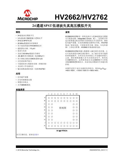
| Package Type | 64-ball VFBGA |
| Peak Analog Signal Current per Channel | 2.0A |
The HV2762 includes an integrated bleed resistor to eliminate voltage buildup on capacitive loads, while the HV2662 does not.
The device supports +40V/-160V, +100V/-100V, and +160V/-40V.
Typical applications include medical ultrasound imaging, piezoelectric sensor drivers, and inkjet printer heads.