
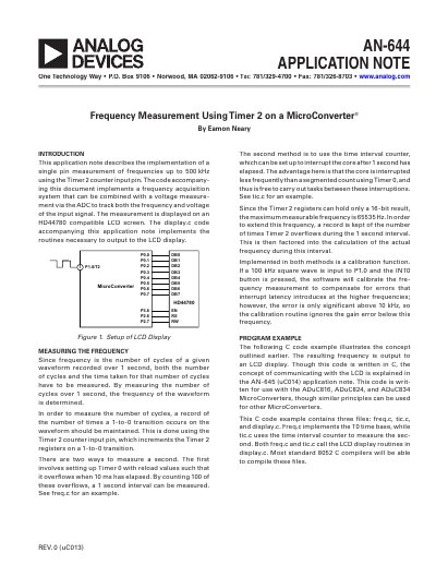
This application note describes the implementation of a single pin measurement of frequencies up to 500 kHz using the Timer 2 counter input pin. The code accompanying this document implements a frequency acquisition system that can be combined with a voltage measure- ment via the ADC to track both the frequency and voltage of the input signal. The measurement is displayed on an HD44780 compatible LCD screen.
This document explains how to measure frequencies up to 500 kHz using the Timer 2 counter input pin on MicroConverter devices. It details two methods for measuring the one-second interval required for frequency calculation: using Timer 0 with 10 ms overflows or using a time interval counter to interrupt the core after one second. The latter method is preferred as it allows the core to perform other tasks between interruptions.
The application note describes the implementation of a single pin measurement of frequencies up to 500 kHz.
Since the Timer 2 registers can hold only a 16-bit result, the maximum measurable frequency is 65535 Hz.
The calibration routine ignores the gain error below 10 kHz.