
AD7781 20-Bit, Pin-Programmable, Low Power, Sigma-Delta ADC Evaluation Board User Guide, is a full-featured evaluation board with a standalone USB interface, various linking options and PC software for control of AD7781.
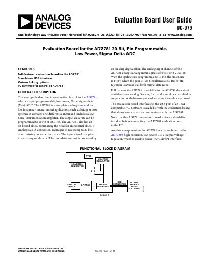
This user guide describes the evaluation board for the AD7781, which is a pin programmable, low power, 20-bit sigma-delta (Σ-Δ) ADC. The AD7781 is a complete analog front end for low frequency measurement applications such as bridge sensor systems. It contains one differential input and includes a low noise instrumentation amplifier. The output data rate can be programmed to 10 Hz or 16.7 Hz. The AD7781 also has an on-board clock, eliminating the need for an external clock. It employs a Σ-Δ conversion technique to realize up to 20 bits of no missing codes performance. The input signal is applied to an analog modulator. The modulator output is processed by an on-chip digital filter. The analog input channel of the AD7781 accepts analog input signals of ±V REF or ±V REF/128. With the update rate programmed to 10 Hz, the rms noise is 44 nV when the gain is 128. Simultaneous 50 Hz/60 Hz rejection is available at both output data rates. Full data on the AD7781 is available in the AD7781 data sheet available from Analog Devices, Inc., and should be consulted in conjunction with this user guide when using the evaluation board. The evaluation board interfaces to the USB port of an IBM- compatible PC. Software is available with the evaluation board that allows users to easily communicate with the AD7781. Note that the AD7781 evaluation board software should be installed before connecting the AD7781 evaluation board to the PC. Another component on the AD7781 evaluation board is the ADP3303 high precision, low power, 3.3 V output voltage regulator, which is used to power the USB/SPI interface.
| Resolution | 20-bit |
|---|---|
| Output Data Rate | 10 Hz or 16.7 Hz |
| RMS Noise | 44 nV |
| Gain | 1 or 128 |
| Power Supply | 5 V via USB or 3.3 V via ADP3303 |
Use link LK15 to select the output data rate. With LK15 in Position 10 Hz, the output data rate is set to 10 Hz. When LK15 is in Position 16.7 Hz, the output data rate is set to 16.7 Hz.
Use link LK16 to select the gain. With LK16 in Position 1, the gain is set to 1. With LK16 in Position 128, the gain of the AD7781 is set to 128.
The ADP3303 is a high precision, low power, 3.3 V output voltage regulator used to power the USB/SPI interface.