
CN-0278 is a Circuits from the Lab™ reference circuit designed and built by Analog Devices to help solve today’s analog, mixed-signal, and RF design challenges. This circuit consists of the AD5700 and AD5422 to provide a 4 mA to 20 mA HART solution with additional voltage output capability.
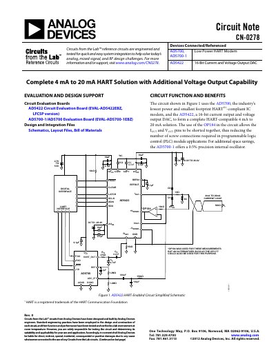
Circuit Note CN-0278 presents a design for a complete HART-compatible 4 mA to 20 mA current output solution. It combines the industry's lowest power HART-compliant IC modem, the AD5700, with the AD5422, a 16-bit current and voltage output DAC. This configuration is particularly useful in programmable logic control (PLC) and distributed control system (DCS) applications where space savings are critical.
The document details how to configure the circuit to meet HART physical layer specifications, including output noise during silence and analog rate of change requirements. It provides guidance on determining external component values for capacitors and resistors to ensure undistorted FSK signal passage and proper attenuation.
The voltage noise measured across a 500 Ω load must contain no more than 2.2 mV rms of combined broadband and correlated noise.
The bandwidth presented to the modem output signal must pass the 1200 Hz and 2200 Hz frequencies.
The low-pass and high-pass frequency cutoff point targets were >10 kHz and <500 Hz, respectively.