
The VRP2 pressure reduction valve is a directly controlled three-way pressure reduction valve for high-level cascading systems, i.e. with pressure relief of the secondary circuit. The valve consists of a housing (1), a control piston (2), a spring (3), an adjustment element (4) and a plug G1/4 (5) as a measuring connection and, if necessary, a check valve. Execution“A” In this execution, the fluid enters the housing from the primary circuit (from the directional valve) through channel A and flows through the piston control edge, where a corresponding pressure reduction takes place. The reduced pressure corresponds to the setting of the control spring. This pressure acts simultaneously on the face of the control piston opposite the spring (the pressure can be measured in the G 1/4 connection.) This creates a static equilibrium at the control piston. If the reduced pressure in the outlet channel changes, a subsequent adjustment is made and the reduced pressure is restored to the desired value. The volume flow from the outlet channel A2 then flows to the consumer. In the opposite direction, the volume flow flows through the check valve, which is connected in parallel to the piston control edge. If the pressure in the valve outlet increases due to consumer overload, the control piston moves further against the spring until the second control edge is opened and the excess volume flow is discharged via channel T. The leakage flow from the spring chamber is discharged in the same way.
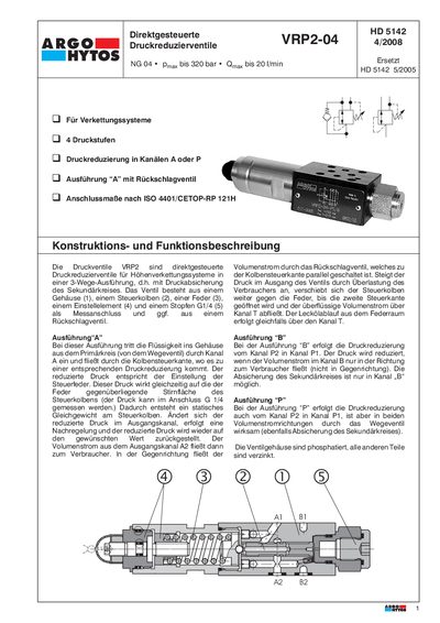
This document is a technical datasheet for the Argo-Hytos VRP2-04 series of directly controlled pressure reducing valves designed for height linkage systems. The valves are available in three configurations: 'A' with a check valve, 'B', and 'P', each offering different pressure reduction capabilities within hydraulic circuits. This manual is written in German.
| Max. Flow Rate | 20 l/min |
|---|
The specified tightening torque for the mounting screws is 5 Nm.
The maximum volume flow rate is 20 l/min.
The maximum operating pressure is 320 bar.
The required minimum oil cleanliness is ISO 4406 (1999), class 21/18/15.