
The C7884 series is a driver circuit specifically designed for the Hamamatsu current-output type NMOS linear image sensors. It features high precision, low noise, and compactness.
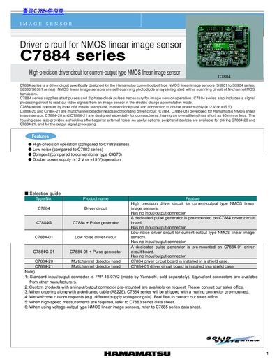
The C7884 series is a high‑precision driver circuit for Hamamatsu current‑output NMOS linear image sensors. It supplies start pulses, 2‑phase clock pulses, and includes a signal‑processing circuit to read out video signals. The driver operates with a double power‑supply configuration and is available in several variants such as C7884‑20 and C7884‑21 for compact multichannel detector heads.
The manual lists electrical specifications (supply voltages, current consumption, master clock frequencies), mechanical dimensions, and detailed pin‑out tables for the 15‑pin D‑sub connector. It also describes the dedicated cable A8226, connector types, and optional accessories. Contact information for Hamamatsu Photonics worldwide is provided at the end of the document.
| Master clock frequency (C7884) | 4 MHz |
|---|---|
| Master clock frequency (C7884‑20/‑21) | 2 MHz |
| Operating temperature range | 0 °C to +50 °C |
| Gain | 0.3 |
The C7884 module uses a 4 MHz master clock, while the C7884‑20/‑21 variants operate at 2 MHz.
Cable A8226 uses a BNC connector for the signal lines (Start, CLK, Trigger, EOS, Data Video) and a UFS‑16B‑01 connector on the board.
Pins provide Data Video, +12 V/+15 V, -12 V/-15 V, Start, CLK, EOS, Trigger, and various ground signals.