
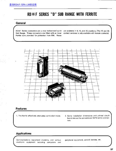
The RD F Series D‑Sub range adds a ferrite core to standard D‑sub connectors for effective EMI protection. Available in 9, 15, and 25‑pin configurations, the connectors retain the same installation dimensions as the conventional RD‑D series.
Technical data include a 3 A current capacity, AC 100 V rated voltage, steel shell with nickel plating, PBT insulation, and phosphor‑bronze solder‑plated contacts. Detailed mechanical dimensions and PCB‑mounting hole patterns are provided for each pin count.
| Current capacity | 3 A |
|---|---|
| Rated voltage | AC 100 V |
| Shell material | Steel |
| Finish | Nickel plating |
| Contact material | Phosphor bronze solder‑plated |
| Contact resistance | ≤25 mΩ at DC 100 mA |
| Withstand voltage | 1‑4 min at AC 1250 Vrms |
| Number of pins | 9, 15, 25 |
The connector is rated for a current capacity of 3 A.
The range is offered with 9, 15, or 25 pins.
The ferrite core effectively attenuates conduction noise, providing EMI protection.