
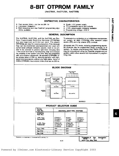
The AMD 8‑bit OTPROM family (Am2764A, Am27128A, Am27256) provides fast access times, low power dissipation and TTL‑compatible I/O. The devices support both interactive and Flashrite programming algorithms and operate from a single +5 V supply.
The handbook includes detailed functional descriptions, pin‑mode tables, absolute maximum ratings, electrical characteristics, and waveform specifications for programming and verification, as well as ordering information and package options.
| Access time | as low as 200 ns |
|---|---|
| Programming voltage | 12.5 V |
| Supply voltage (Ag pin) | 13.50 V to –0.6 V |
| Supply voltage (Vpp pin) | 13.50 V to –0.6 V |
| Output capacitance (typical) | 8‑12 pF |
| Standby current | 25 mA |
| Active current (Am2764A) | 75 mA |
| Package types | 26‑Pin DIP (PD‑028) and 32‑Pin PL‑032 |
Programming mode is entered when a voltage greater than 12.0 V but less than 13.3 V is applied to the Vpp pin.
Standby mode is activated by applying a TTL HIGH signal to the CE input, which places the outputs in a high‑impedance state.
Access times can be as fast as 200 ns, with other options at 250 ns and 450 ns.