
14-Bit Serial Input Voltage-Output DACs
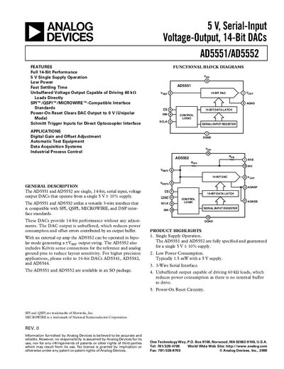
The AD5551 and AD5552 are 14‑bit, serial‑input, voltage‑output digital‑to‑analog converters that operate from a single 5 V supply. They use a versatile 3‑wire interface compatible with SPI, QSPI, MICROWIRE and DSP standards, and feature an unbuffered output that can directly drive 60 kΩ loads.
Key features include single‑supply operation, typical power consumption of 1.5 mW, a maximum serial clock frequency of 25 MHz, and built‑in power‑on reset that clears the output to 0 V in unipolar mode. The devices are offered in SO‑8 and R‑14 packages and include Kelvin‑sense pins for high‑precision reference connections.
| Resolution | 14 Bits |
|---|---|
| Power Dissipation (typical) | 1.5 mW |
| Supply Voltage Range | 4.5 V – 5.5 V |
| Output Impedance (typical) | 6.25 kΩ |
| Maximum SCLK Frequency | 25 MHz |
| Typical Supply Current | 0.3 mA |
The devices operate from a single supply voltage between 4.5 V and 5.5 V (5 V ±10%).
Typical power consumption is about 1.5 mW at a 5 V supply.
The serial interface can operate up to a maximum SCLK cycle frequency of 25 MHz.