
The LT3501 is a dual current mode PWM step-down DC/DC converter with two internal 3.5A switches. It features independent input voltage, feedback, soft-start, and power good pins for each channel, simplifying complex power supply tracking/sequencing requirements. The converters can be synchronized to a common external clock input or a resistor programmable fixed 250kHz to 1.5MHz internal oscillator. The channels maintain a 180° phase relationship at all frequencies, reducing voltage ripple and component size. The programmable frequency allows for optimization between efficiency and external component size. The switch can stay on through multiple clock cycles, only switching off when the boost capacitor needs recharging, resulting in a maximum duty cycle of ~95% and improved minimum input-to-output voltage ratios. Each output can be independently disabled using its own soft-start pin, or the entire part can be placed in low quiescent current shutdown mode using the SHDN pin. The LT3501 is available in a 20-lead TSSOP package with an exposed leadframe for low thermal resistance.
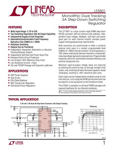
The LT3501 is a dual current‑mode PWM step‑down DC/DC converter with two internal 3.5 A switches. Each channel has independent input, feedback, soft‑start and power‑good pins, allowing flexible tracking and sequencing of power supplies. The device operates over a wide input range of 3.1 V to 25 V and supports a programmable switching frequency from 250 kHz to 1.5 MHz, with antiphase operation to reduce ripple.
The converter is supplied in a 20‑lead TSSOP package with an exposed thermal pad. It offers features such as independent soft‑start, low shutdown current (<10 pA), enhanced short‑circuit protection, and the ability to synchronize both channels to an external clock or an internal resistor‑set oscillator. Detailed electrical characteristics, pin functions, and typical performance graphs are provided for design reference.
| Input voltage range | 3.1 V to 25 V |
|---|---|
| Output current capability per channel | 3 A |
| Switching frequency range | 250 kHz to 1.5 MHz |
| Package type | 20‑Lead TSSOP with exposed leadframe |
| Shutdown current | <10 pA |
| Maximum duty cycle | 95 % |
The LT3501 operates with an input voltage from 3.1 V up to 25 V.
Each of the two regulators can deliver up to 3 A of output current.
Yes, both converters can be synchronized to a common external clock or to a resistor‑programmed internal oscillator.
The device is supplied in a 20‑lead plastic TSSOP package with an exposed thermal pad.