
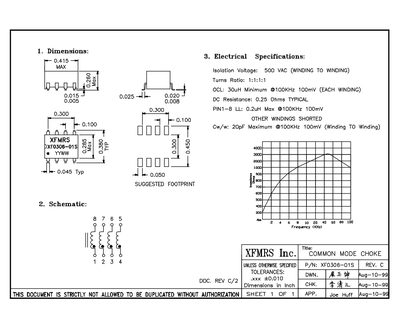
This one‑page datasheet provides the key mechanical and electrical characteristics of the XFMRS XFO306-01S common mode choke. It lists dimensions, inductance per winding, DC resistance, turns ratio, isolation voltage and inter‑winding capacitance.
The document also includes a suggested PCB footprint, schematic reference, and tolerance notes, making it useful for designers selecting the part for EMI filtering applications.
| Inductance (each winding) | 30 µH minimum @100 kHz, 100 mV |
|---|---|
| DC Resistance | 0.25 Ω typical |
| Turns Ratio | 1:1:1:1 |
| Isolation Voltage | 500 VAC winding‑to‑winding |
| Inter‑winding Capacitance | 20 pF maximum @100 kHz, 100 mV |
Each winding provides at least 30 µH at 100 kHz with a 100 mV test condition.
The typical DC resistance is 0.25 Ω.
It is rated for 500 VAC isolation between windings.
The maximum capacitance between windings is 20 pF at 100 kHz, 100 mV.