
This document is the customer acceptance specification for backlight inverters for cold cathode fluorescent lamps. It specifies the scope of use, general specifications, electrical characteristics, reliability, structures and dimensions, and design precautions of the inverter.
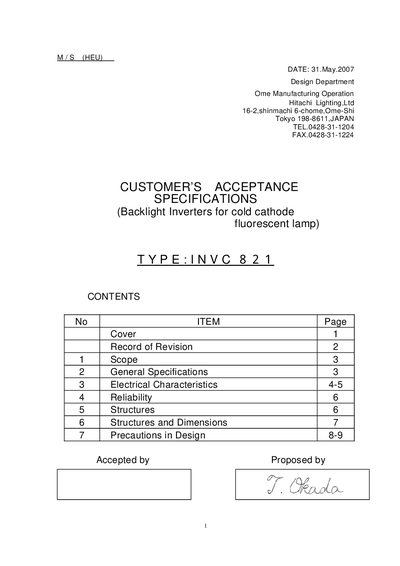
This document specifies the INVC821 backlight inverter intended for use with cold‑cathode fluorescent lamps in LCD modules. It defines the scope, general specifications, electrical characteristics, reliability tests, mechanical structure and design precautions.
Key sections include nominal output power, efficiency, temperature limits, input/output connectors, wiring diagrams and recommended handling procedures to ensure safe and reliable operation.
| Output Power (Nominal) | 3.0 W |
|---|---|
| Cooling Condition | Free air flow |
| Efficiency (minimum) | 85 % |
| Weight (maximum) | 20 g |
| Operating Ambient Temperature | 0 ~ 50 °C |
| Stock Temperature Range | -20 ~ 70 °C |
| Maximum Humidity | 90 % RH |
| Audible Sound Level | 35 dB at 30 cm |
| MTBF (minimum) | 60 000 h |
| Typical Input Current | 510 mA |
| Typical Lamp Current | 4.2 mA |
| Typical Lamp Power | 1.7 W |
| Typical Main Frequency | 75 kHz |
The INVC821 provides a nominal output power of 3.0 W.
It operates from 0 °C to 50 °C and can be stored from –20 °C to 70 °C.
The inverter accepts a typical input of 5.0 V, with a minimum of 4.5 V and a maximum of 5.5 V.
Power must be turned off before connecting or disconnecting CN2, wiring length should not exceed 150 mm, UL1330‑equivalent leads are recommended, and high‑voltage leads must be kept away from shields.