
The TB62201AFG is a dual-stepping motor driver IC for OA equipment using PWM chopper type. It is driven by chopper micro-step pseudo sine wave. Two pairs of 16-bit latch and shift registers are built in the IC to drive two-phase stepping motors. The IC is optimal for driving stepping motors at high efficiency and with low-torque ripple.
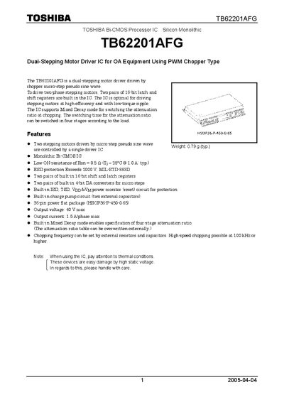
The TB62201AFG is a dual‑stepping motor driver IC that uses PWM chopper technology to drive two‑phase stepping motors with micro‑step pseudo‑sine wave control. It integrates built‑in 16‑bit shift and latch registers, 4‑bit DACs, and mixed decay mode for adjustable attenuation.
The device is supplied in a 36‑pin HSOP package, supports up to 40 V output, 1.5 A per phase, and features low on‑resistance, ESD protection, and a built‑in charge pump. Pin assignments, package dimensions, and soldering guidelines are detailed for reliable integration.
| Maximum output voltage | 40 V |
|---|---|
| Maximum output current per phase | 1.5 A |
| Package type | HSOP36-P-450-0.65 (36‑pin flat package) |
| Typical weight | 0.79 g |
| Maximum chopping frequency | 100 kHz or higher |
The TB62201AFG can deliver up to 1.5 A per phase.
It is supplied in a 36‑pin HSOP36-P-450-0.65 flat package.
The recommended temperature is 230 °C.