
This document provides installation and usage instructions for the control device CB1 PRC-1. The control device is a microcomputer-controlled device used for motor remote control and has the function of precisely setting tension and thrust. During installation, attention should be paid to waterproofing and avoiding prolonged exposure to sunlight.
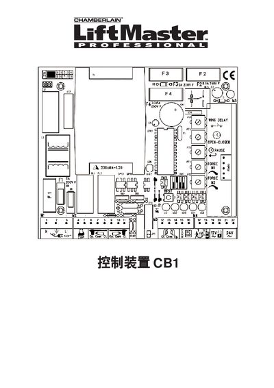
This guide explains how to install the CB1 control unit for garage doors. It details motor mounting, wiring of power and control lines, and optional safety devices such as light curtains and photoelectric sensors. The document also describes how to connect the waterproof distribution box and ensure proper cable cross‑section for both mains and low‑voltage circuits.
Safety measures are emphasized, including protection against moisture, correct fuse selection, and the use of emergency stop switches. Configuration of LEDs, adjustable switches, force potentiometers, and remote control channels is also covered, allowing the installer to fine‑tune door operation and set up wireless remote units. This manual is written in Chinese.
| Mains voltage wire cross‑section | ≥ 1.5 mm² |
|---|---|
| Low‑voltage wire cross‑section | ≥ 0.5 mm² |
| Main fuse (F1) | 5.0 A |
| Auxiliary fuse for 24 V (F2) | 0.5 A |
| Auxiliary fuse for electronic lock (F3) | 2.0 A |
| Logic circuit fuse (F4) | 0.315 A |
| LED1 indicator | Red – normal closing sensor operation |
| LED2 indicator | Red – normal opening sensor operation |
| Maximum remote controllers per channel | 15 |
Seal all openings and ensure that cables and connectors are waterproof; keep the unit away from moisture and standing water.
Use a minimum cross‑section of 1.5 mm² for 100‑230 V wiring.
Up to 15 hand‑controllers can be connected to each channel.
Install a 5.0 A main fuse (F1); larger fuses must not be used.