
MC138 LCD controller board is a re-programmable controller board with RS485 communication interface, 8 outputs, LCD display, 32(8X4) key inputs, 32 K EEPROM, clock function, built-in alarm system, support for i-Control System, etc.
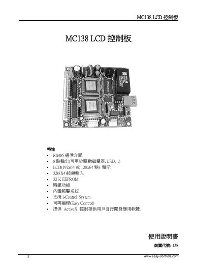
This manual describes the MC138 LCD control board, a RS‑485 based controller with up to 68 output channels and 32 key inputs (8×4 matrix). It includes information on power supply requirements, reset behavior, communication settings, and how to configure the built‑in alarm system.
The document also provides wiring diagrams for the RS‑485 interface, output terminals, and key input connectors, as well as technical specifications such as LCD resolution, EEPROM size, and power consumption. Support resources and software download links are listed at the end. This manual is written in Chinese.
| Number of outputs | 8 (can drive devices, LED) |
|---|---|
| Maximum output current per channel | 300 mA |
| Number of key inputs | 32 (8×4 matrix) |
| LCD resolution | 128×64 or 192×64 |
| Communication interface | RS‑485 |
| EEPROM size | 32 KB |
| Power supply voltage | 8 V to 24 V DC |
| Power consumption (max) | 3 W |
| Dimensions | 85 mm × 84 mm |
The MC138 board uses an RS‑485 communication interface.
The board provides 32 key inputs arranged in an 8 × 4 matrix.
The controller operates from a DC supply of 8 V to 24 V.