
This document introduces the LCD display interface design of MSP430 microcontroller, taking MSP430F435 as an example to explain the principle and application of LCD display in detail. The microcontroller can directly drive LCD display and has powerful LCD display capabilities.
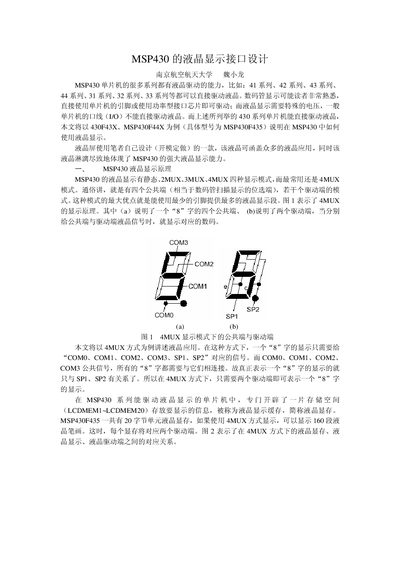
This manual explains the LCD display principles of MSP430 microcontrollers, focusing on the 4‑MUX mode that uses four common pins (COM0‑COM3) and two segment pins (SP1‑SP2). It describes the LCD memory layout (LCDMEM1‑LCDMEM20) and how up to 160 segments can be driven.
The document provides connection diagrams, pin‑out tables, and a complete example program showing how to configure LCDCTL, load segment data, and update LCDMEM registers to display characters such as digits and letters. This manual is written in Chinese.
| Display mode | 4‑MUX |
|---|---|
| LCD memory units | 20 (LCDMEM1‑LCDMEM20) |
| Maximum segments displayable | 160 |
| LCD pins used in 4‑MUX | COM0, COM1, COM2, COM3, SP1, SP2 |
It can display up to 160 segments.
The required pins are COM0, COM1, COM2, COM3, SP1, and SP2.
LCDMEM registers store the segment data that is sent to the LCD for display.