
The document provides information on the electrical wiring diagram, dimensions and installation of QS series reverse sequence switch electrical appliances, as well as their applications, conditions of use, and main technical parameters.
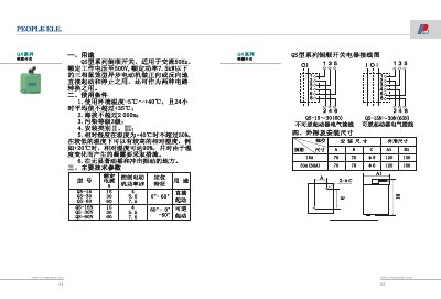
The QS series inverted switch is designed for direct forward or reverse starting and stopping of three‑phase cage‑type asynchronous motors (up to 7.5 kW) on 50 Hz AC supply, and can also be used to switch between two circuit configurations. It is suitable for environments with temperatures from -5 °C to +40 °C, altitude up to 2000 m, and pollution grade 3.
The document includes electrical wiring diagrams for both irreversible (QS‑15N‑30N) and reversible (QS‑15‑30) models, detailed installation dimensions, environmental limits, and key technical specifications such as rated current, motor power, voltage, and humidity requirements. This manual is written in Chinese.
| Rated Voltage | Up to 500 V |
|---|---|
| Operating Frequency | 50 Hz AC |
| Maximum Motor Power | 7.5 kW |
| Rated Current (QS‑15) | 30 A |
| Operating Temperature Range | -5 °C to +40 °C |
| Maximum Altitude | 2000 m |
| Relative Humidity at 40 °C | ≤ 50 % |
| Dimensions (example for QS‑15) | 70 mm × 78 mm × 120 mm |
The switch is rated for up to 500 V and can be used with motors whose power does not exceed 7.5 kW.