
This document introduces the query and setting methods, timing mode, technical parameters, troubleshooting methods, system connection, and indicator lights and buttons of the PJRC-I solar street light controller. The controller has both light control and time control functions, and is controlled by a microcontroller with SOC battery management system. It can intelligently sense the external light intensity, automatically turn on the lighting when it gets dark, and automatically turn off the lighting at the set time or when it gets bright. At the same time, it can also manage the charging and discharging of the battery, protect the battery, and prevent accidental damage to the controller.
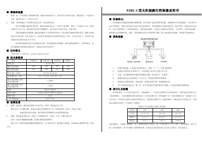
This manual describes the Philips PJRC solar road light controller, which uses a micro‑controller and SOC battery‑management to provide automatic lighting based on ambient light and programmable timing. It supports both light‑control and time‑control modes, protects the battery from over‑discharge, and includes PWM float‑charge and IP22 environmental protection.
The document covers how to query and set operating times using the RESET button, proper system wiring, indicator functions, technical specifications, and fault handling procedures such as low‑battery warnings and load overload protection. This manual is written in Chinese.
| System voltage | 12/24/48 V |
|---|---|
| Maximum charging current | 30 A / 40 A / 50 A / 60 A |
| Maximum discharging current | 30 A / 40 A / 50 A / 60 A |
| Stop‑charge voltage (HVD) | 17 V / 27.4 V / 54.8 V |
| Over‑discharge protection voltage (LVD) | 10‑11 V / 21‑22 V / 42‑43 V |
| Maximum wire gauge | 1 mm² (inside) |
| Charging circuit voltage drop | < 300 mV |
| Discharging circuit voltage drop | < 50 mV |
| Static current | 24 mA |
| Operating temperature range | -25 °C to 55 °C |
| Ingress protection rating | IP22 |
Disconnect the controller from the solar panel and battery for a few seconds; the setting reverts to the default light‑control mode automatically.
A red battery indicator shows insufficient battery voltage. Cut power, press Reset to reset the controller, charge the battery, then reconnect the load.