
AD800 synchronous controller operation manual, detailed introduction of the controller wiring, use, setting methods, etc.
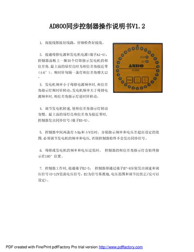
This manual explains how to connect the AD800 synch controller to the bus and generator according to the wiring diagram, and describes the meaning of the phase‑difference indicator lights. It also details the conditions for generating a sync signal and the output of speed and voltage control signals.
The document includes the controller's setting program, parameter tables for voltage and frequency tolerances, gain settings, and RS‑485 interface information, as well as the physical dimensions of the unit. This manual is written in Chinese.
| External dimensions | 96 mm × 96 mm × 70 mm |
|---|---|
| Opening dimensions | 92 mm × 92 mm |
| Generator voltage range | AC 180‑250 V |
| Bus voltage range | AC 180‑250 V |
| Voltage tolerance upper limit | 8 V |
| Voltage tolerance lower limit | 2 V |
| Frequency tolerance upper limit | 0.02 Hz |
| Frequency tolerance lower limit | 0.02 Hz |
| Closing advance angle | 6° |
| Speed gain setting | 3 |
| Voltage gain setting | 3 |
Press and hold the “国加” button for about 8 seconds until all phase‑difference indicator lights flash, then release the button to enter the setting state.
Connect terminals B2‑3 for the signal ground; the controller outputs speed and voltage control signals on terminals B7‑8 as 0‑12 V DC.
The phase‑difference indicator rotates clockwise.