
GAVR-8A is a sealed electronic device used to adjust the excitation current of the generator to stabilize the output voltage. It has the characteristics of wide input voltage range, high maximum output current, and low frequency protection.
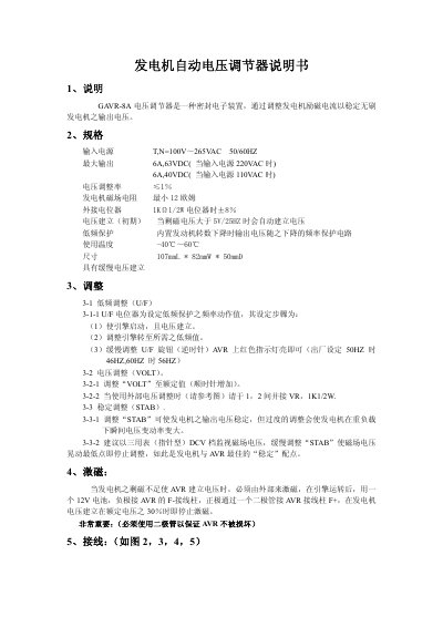
This manual describes the GA VR-8A sealed electronic voltage regulator, which stabilizes the output voltage of a brushless generator by adjusting the excitation current. It includes an overview of the device, its purpose, and safety notes.
The document lists electrical specifications, wiring connections, and step‑by‑step adjustment instructions for low‑frequency protection (U/F), voltage setting (VOLT), and stability control (STAB). It also explains external excitation using a 12 V battery and diode, and provides wiring diagrams for various input voltages. This manual is written in Chinese.
| Input voltage | 100 V ~ 265 V AC 50/60 Hz |
|---|---|
| Maximum output (220 V AC input) | 6 A, 6.3 V DC |
| Maximum output (110 V AC input) | 6 A, 4.0 V DC |
| Voltage adjustment rate | ≤ 1 % |
| Minimum generator field resistance | 12 Ω |
| External potentiometer | 1 kΩ 1/2 W |
| Operating temperature range | -40 °C ~ 60 °C |
| Dimensions | 107 mm L × 82 mm W × 50 mm D |
Start the engine and let the voltage establish, then turn the U/F potentiometer counter‑clockwise until the red indicator on the AVR lights.
Turn the VOLT knob clockwise to increase the output voltage until the desired rated value is reached.
Monitor the generator field voltage with a DC voltmeter and slowly turn the STAB knob until the voltage fluctuation is at its minimum, then stop adjusting.
Connect a 12 V battery with its negative lead to the AVR F‑ terminal and its positive lead through a diode to the AVR F+ terminal after the engine starts; stop when the generator voltage reaches about 30 % of the rated value.