
ExATS9M Automatic Transfer Switching Equipment Installation Manual, introduces the product's packing list, preparation work, operation instructions, appearance and installation dimensions and installation steps, wiring, operating environment, technical parameters, common fault troubleshooting methods and other content.
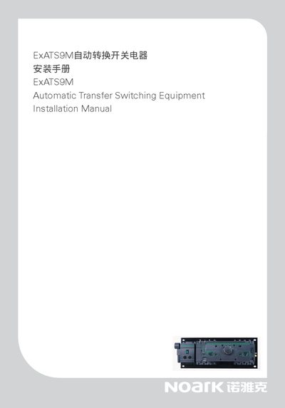
The manual begins with safety warnings, emphasizing that the device must be installed with the control panel in the OFF position, that live parts must not be touched, and that no modifications to the wiring are allowed. It then details the mechanical installation, including mounting screw sizes, torque values, and the order of fastening the chassis and controller.
Subsequent sections cover electrical connections for three‑phase and four‑phase configurations, dimension drawings for the main unit and controller, and a troubleshooting chapter that lists common fault symptoms and their probable causes. The guide ends with manufacturer contact information and a note that the content may be updated. This manual is written in Chinese.
| Mounting screw size | M8×50 (ExATS9M1/2), M12×50 (ExATSgM3, ExATS9M45) |
|---|---|
| Installation torque | 10 Nm (initial), 18 Nm (final) |
The control panel must be set to the OFF position, live metal parts must not be touched, and the wiring must not be altered; the manufacturer is not liable for damage caused by ignoring these instructions.
The switching delay parameter can be set according to user requirements during installation.
A non‑illuminated common source indicator lamp indicates a possible fault in the common source circuit or a wiring issue.