
This document provides the operating instructions for the +GF+ SIGNET 2551 electromagnetic flow meter from Georg Fischer Piping Systems Ltd. It includes a quick start guide, product specifications, installation of fittings, selection of installation location, construction of the 2551 flow meter, technical tips for installation and grounding, wiring of the 4-20mA or frequency/digital signals, preparation and configuration of the user system, use of the i-Go converter and debugging tool, setting of average and sensitivity values, calibration data, maintenance, and ordering information.
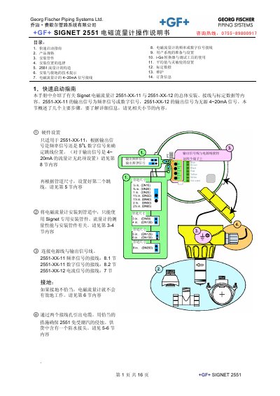
The manual provides a quick‑start guide, detailed product specifications, and step‑by‑step instructions for installing the SIGNET 2551 flow meter. It explains how to select appropriate installation fittings, choose the correct pipe size, and set up the meter in the field.
Further sections cover wiring for 4‑20 mA, frequency or digital signals, grounding techniques, use of the i‑Go conversion and debugging tools, averaging and sensitivity settings, calibration data, routine maintenance, and ordering information for accessories and spare parts. This manual is written in Chinese.
| Sensor body material | PP, 316L SS |
|---|---|
| Power supply for 4~20 mA signal | 21.6~26.4 VDC, max 22.1 mA |
| Flow range | 0.05 m/s – 10 m/s |
| Linearity | ±1 % +0.01 m/s |
| Repeatability | ±0.5 % at 25 °C |
| Maximum cable length | 300 m (1000 ft) |
| Maximum loop impedance | 300 Ω |
| Operating temperature | -10 °C to +70 °C |
| Maximum working pressure | 10.3 bar @ 25 °C |
The 4‑20 mA output needs a supply of 21.6 VDC to 26.4 VDC with a maximum current of 22.1 mA.
The 2551 supports pipe diameters ½"–4" for the P0/W0 versions and 5"–8" for the P1/W1 versions.
Using the i‑Go tool, the averaging time can be set; the factory default is 14 seconds.