
SZD-S-2BF and SZD-S-4BF liquid level regulators are suitable for 1-35T/h, pressure ≤2.5Mpa of various boiler drum water level automatic regulation. They can automatically adjust the water supply and continuously supply water to make the boiler's evaporation rate and water supply rate approach a relatively stable state to maintain the boiler drum water level at a normal position.
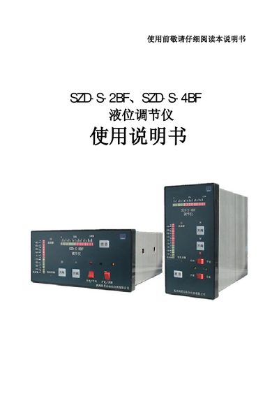
The SZD‑S‑2BF (horizontal) and SZD‑S‑4BF (vertical) are single‑liquid level regulators designed for boiler water‑level control up to 35 T/h and pressures ≤2.5 MPa. The system consists of an inductive float sensor, the regulator unit, an electric control valve and a pump, providing level display, audible/visual alarms and contact outputs.
The manual details system features, technical specifications, wiring diagrams, installation steps, adjustment procedures for level, output current and valve position, as well as safety precautions and ordering information. This manual is written in Chinese.
| Working pressure | ≤2.5 MPa |
|---|---|
| Sensor temperature range | ≤250 °C |
| Relative humidity | ≤85 % |
| Supply voltage | ≈220 V ± 15 % 50 Hz |
| Power consumption | <10 VA |
| Level display range | -50 mm ~ +50 mm or 0 ~ 100 mm (adjustable) |
| Alarm output voltage/current | ≈220 V, 10 A (alarm contacts) |
| Valve feedback signal | 0‑10 mA or 4‑20 mA (DKZ310/DKJ310) or resistance |
| Instrument dimensions (horizontal) | 80 × 160 × 160 mm |
| Instrument dimensions (vertical) | 160 × 80 × 160 mm |
Adjust the low‑level potentiometer W1 until the low‑level alarm lamp and buzzer activate and the low‑alarm relay closes.
The regulator can output either 0‑10 mA or 4‑20 mA; the selection is made with the K5 switch.
Select the valve feedback type with switch K6: position I for DKZ310 (0‑10 mA/4‑20 mA) or position R for ZAZ‑25 (resistance).
Mount the inductive float sensor vertically, keep its axis perpendicular to the liquid surface, limit tilt to ≤2°, and install a drain pipe with a valve.