
The working principle of CF series flow switch is to use the built-in magnet of float flowmeter float to move to the red arrow mark of the detector, so that the magnetic switch inside the detector is activated, and the flow position signal is issued and maintained to complete the flow judgment.
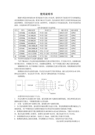
The CF series flow switches work by using a float with an internal magnet that moves to a detector marked by a red arrow. When the float reaches the detector, the indicator light turns on and the internal relay’s normally‑open contact closes, providing a flow‑position signal that can be connected to a PLC or control circuit.
The manual includes a model selection table covering ten variants with different measurement ranges, instructions for adjusting the detection position, details of the power‑loss memory circuit (which retains the float position for up to 45 minutes), and wiring guidelines recommending shielded cable and proper polarity for the four‑core connector. This manual is written in Chinese.
| Power supply | DC 24 V, current < 1 A |
|---|---|
| Contact rating | DC 30 V/1 A or AC 125 V/0.5 A (derate for higher voltage) |
| Memory retention time | 45 minutes |
| Recommended cable | Shielded cable for extension leads |
| Body dimensions | 45 mm × 280 mm (standard for most models) |
When the float rises to the detector’s red‑arrow position, the indicator lamp lights and the internal relay’s normally‑open contact closes.
The built‑in power‑loss memory can retain the float position for up to 45 minutes.
The contacts are rated for DC 30 V/1 A or AC 125 V/0.5 A; for higher voltages the current must be derated accordingly.