
This report introduces the features and characteristics of the Cisco Meraki 3450 series switches.
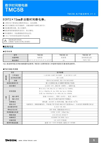
This manual describes the TMCON TMC5B digital time relay, a DIN 72×72 mm multifunction timer with high‑visibility LED display, large square keys, keyboard lock, wiring protection cover, data storage and power‑off memory. It details the device's technical parameters, mounting dimensions, and panel layout.
The document includes wiring diagrams, function‑mode setting flowcharts, and operation mode descriptions (UP/DOWN timing, various output modes). Safety and installation notes advise proper separation of signal and power cables, load limits, and power‑cycle timing to ensure reliable performance. This manual is written in Chinese.
| Auxiliary voltage range | AC/DC 12–24 V 85–110 % |
|---|---|
| Relay contact rating | AC250 V 3 A (resistive load) |
| Insulation voltage | AC2000 V 50/60 Hz for 1 min |
| Operating temperature | -10 °C to +55 °C (non‑freezing) |
| Storage temperature | -25 °C to +65 °C (non‑freezing) |
| Time range setting | 0.01 s to 9999 h |
| Power‑off memory retention | EEP‑ROM data retained >10 years |
The timer can be set from 0.01 seconds up to 9999 hours.
Signal and power lines should be kept separate from high‑voltage or high‑current lines and kept as short as possible to avoid noise and false operation.
The contacts are rated for AC250 V at 3 A for resistive loads.
Data is stored in EEPROM and remains for more than ten years without power.