
This report introduces the features and characteristics of a certain electronic device produced by a certain company.
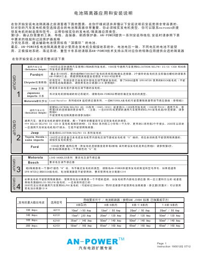
The guide provides step‑by‑step instructions for mounting the battery isolator, selecting the correct wiring and fuse, and connecting it to the vehicle alternator. It also lists the tools and safety precautions needed before beginning the installation.
Installation steps cover verifying alternator type, routing the isolator’s “A”, “2”, “E”, and “R” terminals, attaching the appropriate fuse, and performing an electrical test to confirm correct voltage readings on each terminal. This manual is written in Chinese.
| Wire size for 50 A circuit | 210 mm / 50 A |
|---|---|
| Wire size for 120 A circuit | 220 mm / 120 A |
| Maximum alternator output current (example model) | 200 A |
| Recommended fuse rating | 6 A |
You need a 1/8" drill, screwdriver, wrench, appropriate connectors, and a fuse that meets the current rating shown in the wiring table.
Use a wire length of 210 mm with a 50 A rating (or 212 mm / 50 A as listed).
You must verify the alternator type with AN‑POWER and provide the manufacturer and model; the isolator is designed for alternators that ground to the negative side and have compatible connector pins.
Perform an electrical test: with the engine off, the #1 column should read the main battery voltage, #2 the auxiliary battery voltage, and the E and R columns should read 0 V or the expected range.