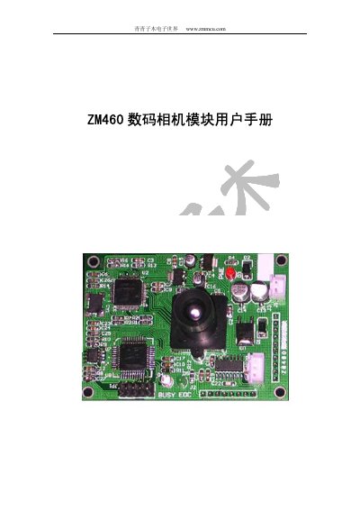
ZM460 digital camera module is an embedded camera device with built-in JPEG compression function and digital output. It has multiple resolutions and interface options, suitable for non-real-time digital image acquisition scenarios.
About this manual
The ZM460 digital camera module integrates a CMOS sensor, JPEG encoder and flexible I/O. It supports three image resolutions (160×128, 320×240, 640×480) and offers RS232, TTL and 8‑bit parallel interfaces for easy MCU integration. Power can be supplied via +5 V or 7.5 V‑12 V with polarity protection, and the module provides BUSY and EOC status signals.
The manual describes power connections, pin definitions, trigger pins (ACT1 for single‑frame, ACT2 for continuous capture), serial and parallel communication settings, sensor specifications (OV7640), lens options, mechanical dimensions and timing diagrams. A PC test software is also available for evaluation. This manual is written in Chinese.
What's inside
- Function Overview
- Typical Applications
- Power Supply
- Status Output Pins
- Trigger Pins
- Serial Interface
- Parallel Interface
- CMOS Sensor
- Lens
- Connector Pinout
Specifications
| Image Resolutions | 160×128, 320×240, 640×480 |
|---|
| Power Options | +5 V or 7.5 V‑12 V |
|---|
| Sleep Current | <1 mA |
|---|
| External +5 V Range | 4.85 V‑5.25 V |
|---|
| Minimum Supply Current | ≥100 mA (+5 V) |
|---|
| Minimum Supply Current | ≥150 mA (7.5 V‑12 V) |
|---|
| CMOS Sensor Model | OV7640 |
|---|
| Standard Lens Focal Length | 6 mm |
|---|
| Lens Mount Diameter | 12 mm |
|---|
| Parallel Output Speed | 0.96‑5.76 KB/s |
|---|
Frequently asked questions
How do I trigger a single image capture?
Pull the ACT1 pin low; the module captures one picture and then ignores further ACT1 changes until the frame is finished.
What power supplies can be used with the ZM460?
The module can be powered either from a +5 V source or from a 7.5 V‑12 V source, both with polarity protection.
How can I change the image resolution?
Set the desired resolution via the serial interface; the setting is stored in EEPROM and retained after power‑off.
What does the BUSY status line indicate?
When BUSY is low (LED on), the module is busy processing and cannot accept new commands; it returns high when idle.