
This document introduces the components and usage of the counter and digital display in Experiment 8. The components include a decimal counter 7490, a seven-segment decoder 7447, and a common anode seven-segment LED display. The purpose of the experiment is to familiarize students with and use common counters, and to display numbers using a seven-segment decoder and seven-segment LED display. In addition, it explains how to use resistors to create a simple digital-to-analog converter.
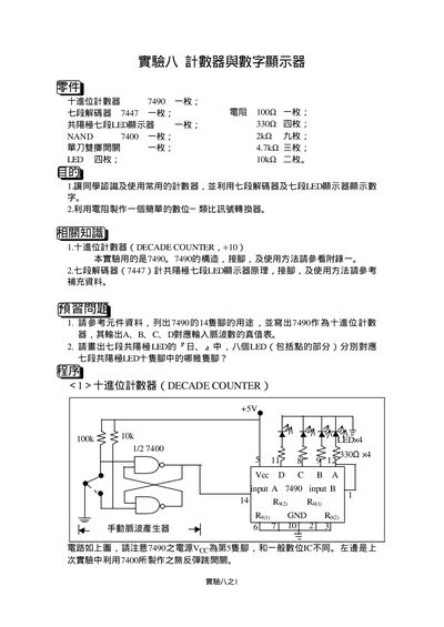
The manual introduces a digital counter project that uses a 7490 decade counter, a 7447 BCD‑to‑7‑segment decoder, and a 7400 NAND gate array. It explains the purpose of the experiment, the required components, and basic theory behind the circuits.
Step‑by‑step procedures guide the user through wiring the circuit, verifying the counting sequence, and extending the design to a simple digital‑to‑analog converter using resistor networks. The document also includes troubleshooting questions and expected output values. This manual is written in Japanese.
| Resistor values | 100 Ω, 330 Ω, 2 kΩ, 4.7 kΩ, 10 kΩ |
|---|---|
| Decade counter IC | 7490 |
| 7‑segment decoder IC | 7447 |
| NAND gate IC | 7400 |
The manual aims to teach how to use a decade counter and a common‑anode 7‑segment display, and to build a simple digital‑to‑analog converter.
Four NAND gates are needed to construct the 7490 decade counter.
Yes, the document describes a simple D/A converter built from the counter output and a resistor network.