
This document introduces the wiring diagram of the display screen system and common troubleshooting methods, including the wiring of the bar screen and the handling of the scanning signal section. It also provides solutions to various common fault phenomena.
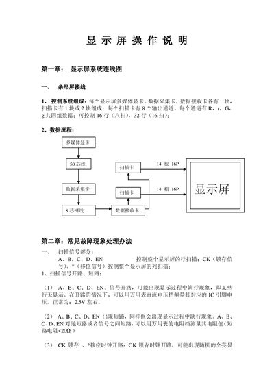
This document provides detailed wiring diagrams for LED display systems, describing the connections of multimedia graphics cards, data acquisition cards, scanning cards and control signals. It lists the voltage levels for control signals (A‑D, EN, CK, etc.) and explains how to measure them.
The guide also includes extensive fault diagnosis steps, recommended test tools (digital multimeter, logic probe, suction tool, soldering iron, screwdriver) and repair methods for common issues such as open/short circuits, missing rows or columns, and driver IC failures. This manual is written in Chinese.
| Control signal voltage (A, B, C, D) | ≈2.5 V |
|---|---|
| EN signal voltage | 0 V or ≈2.5 V |
| CK (latch) clock voltage | ≈4.0 V or ≈2.5 V |
| Data signal voltage (R, r, G, g) | ≈4.1 V |
| Microcontroller supply voltage (single‑chip control) | 4.96 V – 5.10 V |
Each of the A, B, C, D control signals should be about 2.5 V.
Measure the voltage on the corresponding IC pin with a multimeter on DC voltage mode; a normal reading is around 2.5 V.
Prioritize fixing the short circuit, using the multimeter’s resistance or diode‑drop mode while the circuit is powered off.