
M10, M11, M12, M25 Vishay Draloric Thin Film Rectangular Resistor Chips with metal film layer, protective top coat, pure tin on nickel barrier layer, low temperature coefficient and tight tolerances.
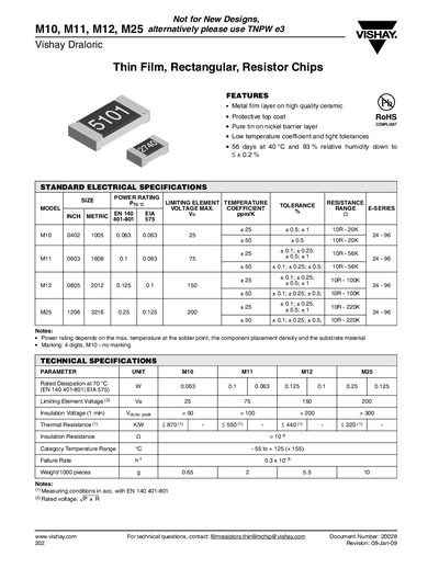
This datasheet provides specifications, dimensions, packaging and performance data for Vishay's thin‑film rectangular resistor chips in the M10, M11, M12 and M25 series. It includes electrical parameters such as limiting element voltage, insulation voltage, thermal resistance and temperature coefficient, as well as mechanical details like size and solder‑pad dimensions.
The document also lists recommended packaging formats, test results, and compliance information. It notes that the parts are not intended for new designs and suggests using the TNPW e3 series as alternatives.
| Limiting Element Voltage | M10 25 V, M11 75 V, M12 150 V, M25 200 V |
|---|---|
| Insulation Voltage (1 min) | >50 V (M10), >100 V (M11), >200 V (M12), >300 V (M25) |
| Thermal Resistance | <870 K/W (M10), <550 K/W (M11), <440 K/W (M12), <2200 K/W (M25) |
| Insulation Resistance | >10 GΩ |
| Category Temperature Range | -55 °C to +125 °C (+155 °C) |
| Failure Rate | 0.3 × 10⁻⁹ failures per hour |
| Weight per 1000 pieces | 0.65 g (M10), 2 g (M11), 5.5 g (M12), 10 g (M25) |
For new designs, Vishay recommends using the TNPW e3 series instead of the M10, M11, M12, or M25 parts.
M11 chips are supplied on a reel with 180 mm (7 in) width, 1000 pieces per reel, packaging code P41.
Endurance is tested for 1000 h at 70 °C with a 1.5 h on / 0.5 h off cycle, meeting a tolerance of <202 %.
The M12 series has a limiting element voltage of 150 V.