
This document is the user manual for the NCP1215-EVM evaluation kit from Wuhan Liyuan Information Technology Service Co., Ltd. The NCP1215-EVM is an evaluation kit for the ON Semiconductor NCP1215 product, suitable for evaluating the switch-mode power controller NCP1215 chip. The NCP1215 is a low-cost current feedback switch-mode power controller that can be used to create small power switch-mode power supplies or charging adapters. The evaluation board can be configured as an AC-DC adapter or a charging adapter with constant current characteristics.
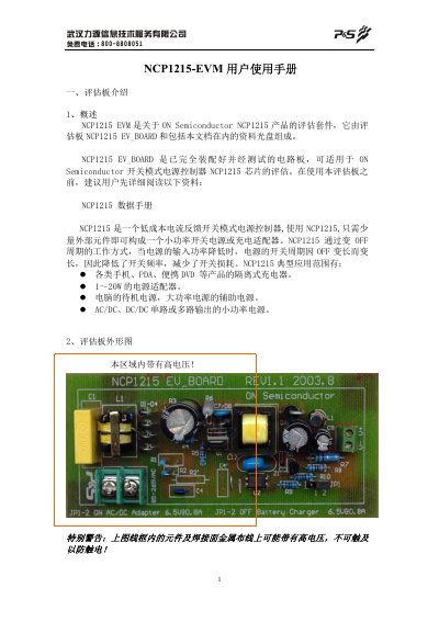
This manual describes the NCP1215-EVM evaluation board, a fully assembled and tested PCB that allows evaluation of the NCP1215 switching‑mode power controller. The board can be configured as a low‑power AC‑DC adapter or a constant‑current charger by setting the P1 jumper.
The document includes board dimensions, PCB layout, schematic, connection instructions, configuration for AC‑DC operation (input 85‑264 V AC, 6.5 V output, up to 800 mA, ~70 % efficiency) and charger mode, as well as a complete component list with part numbers and values. This manual is written in Chinese.
| Input voltage range | 85 ~ 264 V AC |
|---|---|
| Output voltage | 6.5 V ±5 % |
| Maximum continuous output current | 800 mA |
| Typical conversion efficiency | 70 % |
| Switching frequency (max) | < 50 kHz |
The board accepts an AC input voltage from 85 V to 264 V.
Short the P1 jumper pins 1‑2; the board then operates as a low‑power AC‑DC switching power supply.
Open the P1 jumper (leave pins 1‑2 unconnected); the board then works as a constant‑current charger.
The board can deliver up to 800 mA continuous output current.