
The LTC4442/LTC4442-1 is a high frequency gate driver designed to drive two N-channel MOSFETs in a synchronous buck DC/DC converter topology. The powerful driver capability reduces switching losses in MOSFETs with high gate capacitance. The LTC4442 features a separate supply for the input logic to match the signal swing of the controller IC. If the input signal is not being driven, the LTC4442 activates a shutdown mode that turns off both external MOSFETs. The input logic signal is internally level-shifted to the bootstrapped supply, which may function at up to 42V above ground. The LTC4442 contains undervoltage lockout circuits on both the driver and logic supplies that turn off the external MOSFETs when an undervoltage condition is present. The LTC4442 and LTC4442-1 have different undervoltage lockout thresholds to accommodate a wide variety of applications. An adaptive shoot-through protection feature is also built-in to prevent power loss resulting from MOSFET cross-conduction current. The LTC4442/LTC4442-1 are available in the thermally enhanced 8-lead MSOP package.
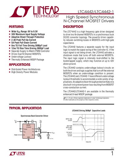
The LTC4442 family provides a high‑frequency gate driver for driving two N‑channel MOSFETs in a synchronous buck converter. It features a separate logic supply, adaptive shoot‑through protection, and undervoltage lockout to improve efficiency and reliability.
The device is offered in an 8‑lead plastic MSOP package with an exposed die pad for thermal performance. Pin functions include high‑side and low‑side gate outputs, a bootstrapped supply, and a dedicated shutdown mode when the input pin is left floating.
| Maximum Input Supply Voltage | 38 V |
|---|---|
| Peak Pull‑Up Current | 2.4 A |
| Peak Pull‑Down Current | 5 A |
| UVLO Rising Threshold (Vcc) | 2.75 V |
| Package | 8‑Lead Plastic MSOP |
| Number of Pins | 9 (including exposed pad) |
The typical rise time is 12 ns.
The driver can source up to 5 A of peak pull‑down current.
It is supplied in an 8‑lead plastic MSOP package with an exposed die pad.