
WP-100SB speed meter user manual, introduces the overview, main technical performance, operation instructions, parameter setting, parameter calculation method, and an example of setting coefficient and parameters.
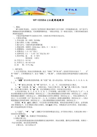
The WP-100SB turn speed table is an intelligent speed‑measurement instrument that uses a single‑chip microprocessor. It works with two magnetic speed sensors to display individual speeds and the speed ratio, suitable for monitoring two points on mechanical equipment.
The manual describes the technical specifications, step‑by‑step operation, parameter configuration using the SET, ◄ and ▲ keys, and wiring connections for power and sensor inputs. It also lists the accessories included in a complete set. This manual is written in Chinese.
| Supply voltage | 85–285 V, 50/60 Hz |
|---|---|
| Input frequency range | 0.5 Hz–10 000 Hz |
| Input signal | Matches magnetic speed sensors |
| Speed measurement range | Dual‑channel 30–9999 r/min (ratio 0–99.99) |
| Measurement accuracy | ±0.03 % (digital display) |
| Factory coefficient setting | 1.0 |
| Sampling time | 0.1–5.0 s (factory default 1.0 s) |
| Operating temperature | 0–50 °C |
| Relative humidity | ≤85 % |
| Opening size | 92 × 92 mm |
| Dimensions | 96 × 96 × 110 mm |
| Weight | <1.0 kg |
When powered on, the display shows “8888.” and “88.88”. If no signal is detected within 5 seconds, it changes to “0” and “8888”.
Connect +12 V and 0 V to the sensor power inputs; S1 and 0 V to the two outputs of magnetic sensor 1, and S2 and 0 V to sensor 2. Connect L and N to the instrument’s AC power (85–285 V, 50/60 Hz).