
This document is an introduction and user guide for CHV100 series closed-loop vector control inverter. The document includes safety precautions, technology features, selection guide, parts description, installation and disassembly, wiring, operation, and detailed function description.
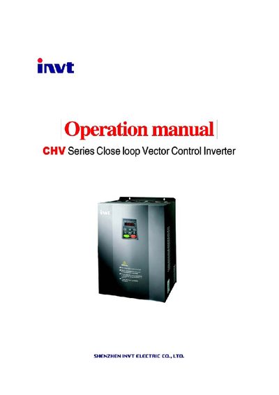
The Invt Electric CHV100 Series Close Loop Vector Control Inverter manual covers all aspects needed to safely install, configure, and operate the inverter. It includes safety precautions, unpacking inspection, disassembly, and detailed installation instructions.
Key sections describe wiring diagrams, control functions, troubleshooting procedures, and routine maintenance. The document also lists function parameters, communication settings, and extension card options to help users customize the inverter for their applications.
| Input Voltage Range | 1140/690/380/220V ±15% |
|---|---|
| Input Frequency Range | 47~63 Hz |
| Output Frequency Range | 0~400 Hz |
| Rated Power (example model CHV100‑045G‑4) | 45 kW |
| Overload Capacity | 60 s at 150 % rated current |
| Starting Torque | 150 % of rated torque at 0.5 Hz (SVC) |
The inverter accepts an input voltage of 1140 V, 690 V, 380 V or 220 V with a tolerance of ±15 %.
Disconnect the default +24 V connection and connect the PW terminal to the external power supply as described in the external braking unit section.
The inverter supports baud rates of 1200, 2400, 4800, 9600, 19200, and 38400 bps, selectable via the PC.01 function code.
It can tolerate a 150 % overload for 60 seconds and a 180 % overload for 10 seconds.