
This document is the user manual for the RIM-0019 electronic fault indicator from Da Tong Corporation. The document provides information on the precautions for use, type description, operation logic flowchart, and specifications of the power supply.
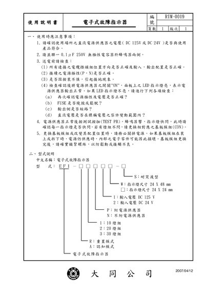
This manual explains how to install and safely operate the RIM-0019 electronic fault indicator. It includes precautions for power supply voltage, wiring checks, and steps to verify correct LED operation before testing.
The document also details the indicator’s lamp configurations, logic flow diagrams for normal, test, and fault modes, and the specifications of the optional power supply units, including input/output voltages, current limits, short‑circuit protection, and efficiency. This manual is written in Chinese.
| Input voltage | DC 125 V or DC 24 V |
|---|---|
| Lamp size (large) | 24 × 48 mm |
| Lamp size (small) | 24 × 24 mm |
| Power supply PS 125‑S input voltage | DC 125 V (±20 %) |
| Power supply PS 125‑S output voltage | DC 12 V (±20 %) |
| Power supply PS 24‑S input voltage | DC 24 V (±20 %) |
The indicator can be powered by either DC 125 V or DC 24 V, depending on the system.