
The AMDP-X/E7 series motor protection device has the protection functions of ground fault, short circuit, phase loss, jamming, unbalanced current, and overload. It also has current, voltage, frequency, and power factor analog outputs, which can be used for the protection, control, and monitoring of AC asynchronous motors.
This user manual provides detailed information on the AMDP‑X/E7 series motor protection devices, including fault type signal outputs, 4‑20 mA analog outputs, and parameter configuration for various protection functions. It also covers wiring diagrams for connecting the protector to motor circuits, PLCs, and external devices.
The document includes specific settings for different model variants (E701, E711, E751), self‑reset options, zero‑sequence current handling, and protection time values for overload, short‑circuit, ground, and phase‑loss conditions. This manual is written in Chinese.
| Fault signal outputs D01‑D06 | Ground, short circuit, phase loss, stall, current imbalance, overload |
|---|---|
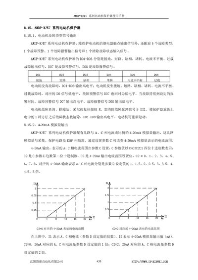
| 4‑20 mA analog output range | Selectable via parameter C (0‑8) representing 1‑5× current |
| Short‑circuit protection time | 0.3 s |
| Ground protection time | 0.6 s (current > set) / 10 s (current < set) |
| Self‑reset function (Parameter B) | Disabled by default (B=0000), enabled when B=1XXX |
Press the reset button R or send a clear‑fault pulse to DI1 to reset the protector.
Set parameter C (C2 value 0‑8) to select the multiplier for the current range represented by the 4‑20 mA signal.